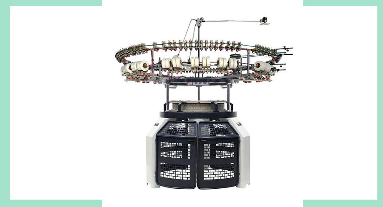
From the title, it is clear that we are going to discuss the Yarn parth diagram of a single jersey circular knitting machine along with the Gearing diagram of a single jersey circular knitting machine.
Inception
A single jersey circular knitting machine is one of the modern machines having one set of needles and another set sinker. Yet needle and sinkers have different cam systems.
Though the cam system is stationery but the cylinder with needles and sinkers are movable. The yarn feeder remains over the m/c and stationery. The machine includes a negative feed system and an electric auto stopper. There are two sensors named upper sensor and lower sensor; to detect yarn breakage.
Objectives:
- To acknowledge the working principle of a single jersey knitting machine.
- To learn the details of the yarn path of the machine.
- To acknowledge the details of the gearing system of the machine.
Required Instruments:
- Lab
- NoteBook
- Pen
- Pencil
Description of Yarn Path Diagram:
- In the creel of the machine, there are cone holders where the cone package remains attached. The yarn starts its journey from the corn package.
- Then the yarn passes through the yarn tube which is made of aluminum. Yarn tube protects the yarn from dust and getting attached to other yarns. Then the yarn comes to the knot catcher.
- The knot catcher prevents multiple yarns from sinking into the machine at once. Because, if multiple threads/ yarns reach the needle at a time, the needle will break down.
- Then the yarn enters the magnetic type tensioner that provides the accurate tension to the yarns.
- From the tensioner, the yarn passes through the upper sensor which lights up if there is any breakage of yarn; in between the creel and yarn wheel.
- Then the yarn moves towards the yarn wheel where a definite amount of yarn remains stored that can continue one cycle.
- From there the yarn passes through a lower sensor that turns the machine off; if the yarn breaks between the yarn wheel and knitting zone.
- At last, crossing the yarn guide the yarn reaches the needle directly
Figure: Yarn path Diagram of Single Jersey Circular Knitting Machine
Description of Gearing Diagram:
- In the machine, there is a motor that transforms electrical energy into mechanical energy. A pulley remains attached with the motor, called a motor pulley.
- When the motor rotates, the motor pulley also rotates. In this manner, the motion gets transferred from motor to motor pulley.
- From the motor pulley, the motion gets transfer to the intermediate pulley through the v-belt.
- Then the motion transfers to the intermediate pinion teeth.
- From there motion transfers to the main transmission shaft pinion through the gear belt.
- Then the motion transfers to the main transmission shaft and under the main gear driver pinion.
- From the main shaft, motion transfers to the VDQ pulley driver pinion.
- Then the motion transfers to the VDQ pulley. Through the VD pulley, the amount of yarn supply to yarn is controlled.
- On the other hand, from under man gear driver pinion motion transfers to the main gear teeth.
- From there motion transfers to the cylinder and it gets rotary motion. Thus the cam, shaft, and needle in the cylinder, also get motion, and the whole process runs perfectly.
Figure: Gearing Diagram of Single Jersey Circular Knitting Machine
Conclusion:
The single jersey machine is a plain fabric producer. For a Textile Engineer, it is a must to have a clear idea about the machine. Through this experiment, we acknowledged many things. Now we can identify and specify the working principle, yarn path diagram, and also gearing diagram of the single jersey knitting machine.
About the writers
Name : Niloy Kundu Bejoy and Asif Hossain
BGMEA University of Fashion and Technology
Batch-201
ID: 201-049-811 and 201-005-811
